
Shielded Cabling Grounding: How to Bond and Test It Right
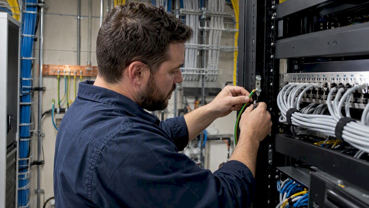
Shielded cabling only works as a shield when it is bonded to the telecommunications grounding system correctly. In a commercial building that usually means the shield of each channel is bonded at the patch panel in the telecom room, the panel is bonded to the rack, the rack is bonded to the busbar, and the whole path is documented and tested. Get one link wrong and you can end up paying for shielded cable that performs worse than plain UTP.
This guide is for IT directors, facilities managers and project managers who have to specify, inspect or sign off on shielded installations in New York City and the surrounding tri-state area. It covers where to ground, why the one-end versus both-ends debate keeps coming up, what bonding hardware to expect, and how to verify the result.
TL;DR
- A shielded channel should be bonded to the telecommunications grounding system at one point, typically the patch panel in the telecom room, so the shield does not create a ground loop.
- Every metallic component in the rack, including shielded patch panels, should tie back to the secondary bonding busbar. Individual #6 AWG conductors per panel are the practice that exceeds the minimum.
- A simple DC continuity test can pass a shield that is actually open. Category 8 work calls for Level 2G testers that check shield continuity along the cable path.
- Shielded does not automatically mean better. In buildings with ground potential differences, the design needs engineering judgment, and every bond needs a label and a record.
Why grounding decides whether shielding helps
A cable shield is a conductive foil or braid around the twisted pairs. According to Fluke Networks, a shield works like a cage that keeps electromagnetic noise out, absorbing that energy and conducting it to ground through a low-impedance path. The last part matters. A shield with no good path to ground has nowhere to send what it captures.
The benefit is real even when the grounding is imperfect. Leviton reports lab testing in which even ungrounded shielded cable gave 20 dB better noise coupling performance than U/UTP cabling. That is a manufacturer’s test, so read it as a direction rather than a promise for your floor. The point stands: grounding is what turns a good shield into a dependable one, and bad grounding is how you lose the advantage.
The NFPA makes the underlying point plainly. Grounding is not just a wire to the earth. As NFPA’s explanation of grounding and bonding describes, the goal is a low-impedance path that lets overcurrent protective devices operate during a fault. For an office manager, that means the grounding behind your network is a safety system, not a performance tweak.
One end or both ends: settling the argument
Search this topic and you will find forum threads that say ground one end, threads that say ground both, and a few that say never to leave an end floating. They are all describing real situations. The disagreement comes from mixing three different kinds of systems.
| Situation | Typical practice | Why |
|---|---|---|
| Structured cabling channel (Cat6A F/UTP, S/FTP, Cat8) in a commercial building | Bond at the patch panel in the telecom room, as the single bonding point of the channel | Avoids ground loops between locations at different potentials |
| Analog sensor or instrumentation cable | Ground one end only, usually at the controller | Prevents circulating current in the signal path |
| Shield for RF shielding effectiveness at high frequency | 360-degree bonding at both ends, with attention to connector design | Long shield stubs and pigtails reduce effectiveness at RF |
For data cabling, the Leviton guidance in our research states that a shielded channel is bonded to the telecommunications grounding system at only one point, typically the patch panel. Grounding both ends can, where voltage potential differs significantly, induce ground currents that interfere with transmission.
That last clause is the reason this is not a one-line rule. Two points in the same building are not always at the same potential. Fluke Networks notes that in large commercial or industrial buildings, differences in ground potential call for an engineered approach, and that grounding a shield at both ends in a high-offset environment can bring in noise instead of removing it.
In practice, for a typical Manhattan office floor, the work-area end of a shielded channel connects to equipment through a shielded jack and a shielded patch cord. The equipment itself has its own safety ground through its power cord. The telecom room end is where the deliberate, documented bond to the building telecommunications grounding system lives.
What the standards ask of you
Two documents shape most commercial grounding work for telecom spaces: the National Electrical Code and ANSI/TIA-607. The NEC is the legal baseline adopted by authorities having jurisdiction. TIA-607 is the standard for how a telecommunications bonding and grounding system is laid out inside a building.
Our research, drawing on Leviton’s patch panel grounding application note, summarizes the expectation this way: shielded systems must be bonded to the telecommunications grounding system so they can safely conduct fault current and limit induced voltages, with all metallic components connected to the secondary bonding busbar (SBB).
The NEC has a dedicated place for this. The code-making panel agenda for the 2026 cycle lists a new article scoped to grounding, bonding and overvoltage protection for Class 2 and Class 3 circuits, optical fiber systems and communications circuits. That is a draft agenda, not the adopted text, so confirm what your jurisdiction has adopted before you design to a particular edition. We cover how recent code changes affect low voltage work in our piece on what NYC IT teams need to know about the NEC 2026 changes.
A licensed electrician and your authority having jurisdiction have the final word on code compliance. If your project touches the building’s main grounding electrode system, bring them in early.
The grounding path, component by component
Think of the path as a chain. The shield is only as good as the weakest link between the cable and the building’s grounding system.
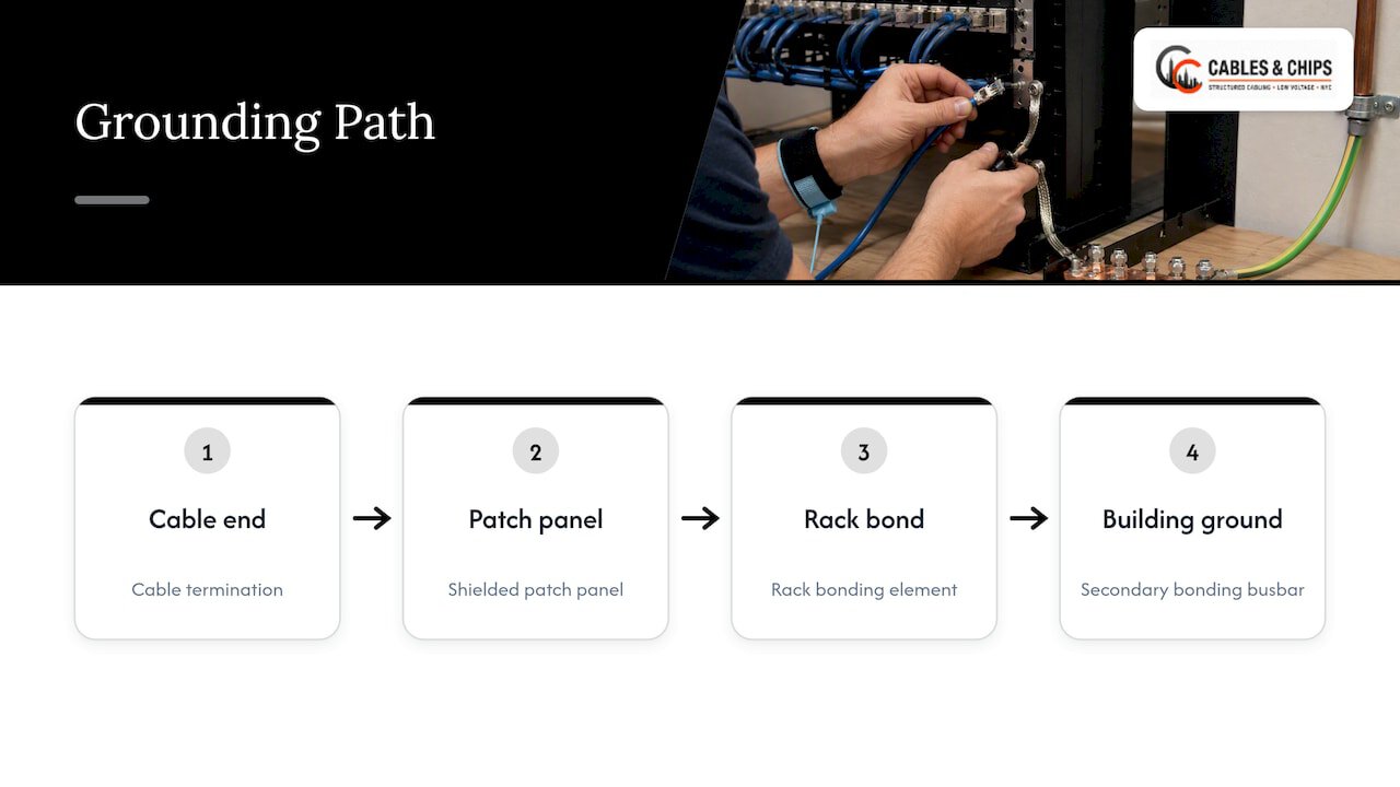
1. The cable and its termination
The shield or drain wire must make a true metal-to-metal connection with the shielded jack or plug. One pitfall that Fluke describes is clamping on the non-conductive foil side, which leaves the cable looking correctly terminated while the shield is effectively disconnected. Check foil orientation and make sure the clamp or drain wire touches the conductive layer.
2. The shielded patch panel
Shielded panels have grounding provisions, such as a lug or earthing lead. Instructions vary by panel model, so the manufacturer’s installation sheet governs. The panel is the usual single bonding point for the channel, so this connection deserves the most care.
3. The rack bonding element
Racks and cabinets are metal and sit in the same fault path. An unbonded rack is a floating metal object, which is one reason we published a separate piece on why you should not leave a server rack floating. Rack bonding is the link between the patch panels and the busbar.
4. The busbar and the telecommunications grounding system
TIA-607 describes the busbars in the telecom room hierarchy, with the secondary bonding busbar serving the room or floor. Conductors run from the SBB back toward the building’s main grounding system. Size, color and routing of those conductors are a design decision with code implications, so they belong to the electrical engineer of record or the electrician who signs off.
Bonding conductors: the minimum and the better practice
The Leviton guidance in our research notes that the common 12 AWG minimum is exceeded by industry best practice of individual #6 AWG unit bonding conductors for each shielded patch panel connection to the rack bonding element.
Why individual conductors rather than daisy-chaining panels? A chain puts the bond of the top panel through the connections of every panel below it. One loose lug and several panels lose their ground at once. A home-run conductor per panel keeps every channel’s bond independent and easy to test.
What this looks like on a typical 48-port shielded panel install:
- Mount the panel in the rack with the rack’s paint or finish removed at the contact points, or with the manufacturer’s bonding hardware.
- Attach one unit bonding conductor to the panel’s grounding point.
- Run it to the rack bonding element, not to another panel.
- Bond the rack to the SBB with its own conductor.
- Label both ends of each conductor.
- Record the path in the as-built documentation.
The specifics (lug type, torque, anti-oxidant compound, conductor color) come from the product instructions and the project specification. Follow them over any rule of thumb from an article, including this one.
How to ground shielded Cat6A and Cat8 without creating a ground loop
A ground loop forms when a shield, or any conductor, connects two points that sit at different electrical potentials. Current then circulates through the shield instead of staying outside the signal path. Noise appears in the channel, often intermittently, and often hard to trace.
The practical rules that follow from the research:
- Pick one bonding point per channel. Make it the patch panel in the telecom room.
- Keep the work-area equipment on its normal safety ground. Do not add a second deliberate shield bond at the outlet.
- Do not mix building grounds across floors by accident. A shielded riser or a metal conduit that touches a different ground can recreate the loop you worked to avoid.
- Survey before you design. On large or mixed-use properties, ask whether different parts of the building share a grounding reference. Fluke’s guidance for high-offset environments is to engineer the solution to the site.
- Plan for Category 8 early. Fluke explains that Category 8 is a shielded system using shielded connectivity and foil-wrapped FTP cable, and that every Category 8 cable is shielded because alien crosstalk would be unmanageable without it.
If your goal is simply to reduce risk in an ordinary office, a well-installed UTP system with good separation from power is often sufficient. Our guide on low voltage and power separation rules explains the spacing that keeps interference down without shielding. Shielded cabling earns its cost near heavy electrical equipment, in dense high-frequency channels, or where a specification requires it.
Temporary power and grounding during buildouts
Grounding questions often start during construction, when the permanent system is not yet energized and trades share temporary power. Equipment such as grounding materials and temporary power distribution rental is common on European sites, and the same principle applies in the United States: temporary distribution should not become an unplanned ground reference for your telecom room. Coordinate with the general contractor on when the telecom room busbar and its connection to the building grounding system will be in place.
Testing: why a pass can be a false pass
Here is the step many projects skip. A shield can look right, bond right on paper and still be open.
Fluke Networks explains that a simple DC resistance check can be fooled. In a data center, the test signal can travel through grounded racks, busbars or adjacent shields and report continuity where the cable’s own shield is broken. The result is a pass that fails in service.
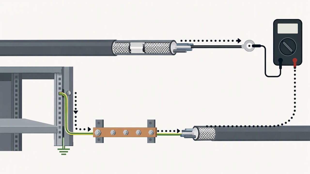
For Category 8 and other high-performance shielded systems, the standard asks for more. ANSI/TIA-1152-A requires testing for screen continuity along the path of the cabling for Level 2G testers. That means a tester capable of AC-based measurement, not an older DC-only continuity tool.
A sensible acceptance plan for a shielded installation includes:
- Visual inspection of each termination, including foil contact.
- Certification testing of every channel or permanent link to the target category.
- Shield continuity verification with a tester that supports it, for systems where that applies.
- A bonding check from each panel to the SBB, with readings recorded.
- A report delivered with the as-built package.
Our as-built documentation guide shows what a complete close-out record looks like.
Document every bond
Bonding conductors are easy to forget because they carry no data. They are also the part someone will need to trace during a future move, add or change. The Leviton note says that clear records and physical labels on bonding conductors are essential and are part of meeting TIA-607 expectations.
At minimum, record:
- The panel, rack and busbar each conductor connects.
- Conductor size and, where relevant, color.
- The test result for each bond, with date.
- Which end of each shielded channel is the bonded end.
If you also use a color scheme for your cabling, our cable color coding field reference can help keep the labeling consistent.
Our perspective
We have installed commercial low voltage systems in New York City for more than 40 years, and the pattern we see most often with shielded cabling is not bad cable. It is a good shielded system installed into a telecom room where nobody owned the grounding.
The first question we ask on a shielded project is who is responsible for the busbar and the conductors to it. Often the answer is a vague mix of the electrician, the IT vendor and the building. We would rather resolve that at the site survey than at certification, when a failed shield test and a ceiling full of finished cable make every fix more expensive.
The second question is whether the project really needs shielding. Shielded does not automatically mean better. If the environment is a standard office with sensible separation from power, a clean, tested and documented UTP system is often the stronger investment. If you are near elevators, heavy motors, or planning Category 8, shielding makes sense and the grounding needs to be designed, not improvised.
Third, we insist that bonding be labeled and documented like every other part of the system. Your network is only as strong as the infrastructure behind it, and that includes the conductors nobody sees.
— Ken
When to bring in a low voltage contractor
Bring one in before cable is ordered if any of these apply:
- You are specifying Category 8 or shielded Cat6A for the first time.
- Your building spans multiple floors, tenants or electrical services. Our guide to cabling in multi-tenant buildings covers the coordination this takes.
- You inherited a telecom room with unlabeled bonding conductors.
- Certification results are inconsistent and nobody can explain why.
Cables & Chips designs, installs, tests and documents structured cabling for commercial offices and secure facilities in New York City, including CAT6 and CAT6A systems, cable testing and certification, and MDF/IDF cleanup. We offer a no-obligation site survey, so the grounding path is reviewed before installation. See our structured CAT6 cabling installation service or our full services list, then schedule a site survey.
Common mistakes to check for
- Shield clamped on the foil side. It looks done and does nothing.
- Panels daisy-chained to one ground wire. One loose lug takes out several channels.
- Both ends bonded in a high-offset building. This can introduce the noise you wanted to remove.
- Pass on a DC continuity test only. The test signal may travel through the rack instead of the shield.
- An unbonded or floating rack. Metal in the fault path with no deliberate connection.
- No labels or records. The next technician has to guess.
FAQ
Where do you connect a shielded cable to ground?
For structured cabling, the usual answer is at the patch panel in the telecom room, bonded through the rack to the secondary bonding busbar. Treat that as the single bonding point of the channel. Always follow the panel manufacturer’s instructions and the project specification.
How do you ground shielded Cat6 cable?
Use shielded jacks and patch cords with continuous shield contact, terminate the shield to the connector’s grounding provision, and bond the shielded patch panel to the rack and then to the busbar. Do not rely on the rack mounting screws alone. Confirm the result with testing, because a visual check cannot show an open shield.
What are the downsides of shielded twisted pair cable?
It costs more, it is stiffer and takes more care to terminate, and it adds a grounding task that has to be designed and documented. Done wrong, it can create ground loops in buildings with differing ground potentials. In a typical, well-separated office, unshielded cabling can be the better value.
Does a DC continuity test prove the shield is good?
No. Fluke Networks warns that the test signal can pass through racks, busbars or neighboring shields and make an open shield appear continuous. For Category 8 systems, the standard calls for testers that verify shield continuity along the cable path.
Sources
- Leviton application note: patch panel grounding
- Leviton tech brief: shielded patch cords in UTP channels
- Fluke Networks: electromagnetic interference mitigation in industrial Ethernet cabling
- Fluke Networks: how to test shield integrity
- Fluke Networks: Category 8 approved, now what
- Fluke Networks: overview of Category 8 cable testing
- NFPA: how grounding and bonding are achieved
- NFPA: NEC Code-Making Panel 5 first draft meeting agenda